AmpDelay Arduino Code

/*
* Amp Delay circuit, based on ‘button’ by DojoDave <http://www.0j0.org&gt;
*
* Control relays turning on power amps when input is detected on pin 2
* When input is gone (receiver off) the relays will turn off
*
*/

int relayPin1 = 6;             // choose the pin for the RELAY
int relayPin2 = 12;             // choose the pin for the RELAY
int relayPin3 = 11;             // choose the pin for the RELAY
int relayPin4 = 10;             // choose the pin for the RELAY
int relayPin5 = 9;             // choose the pin for the RELAY
int relayPin6 = 8;             // choose the pin for the RELAY
int inputPin = 7;               // choose the input pin for receiver
int val = 0;
int val2 = 0;                   // variable for reading the pin status
int onToggle = 0;               // variable so delays don’t occur every cycle
int offToggle = 0;              // variable so delays don’t occur every cycle
int buttonState;

void setup() {
pinMode(relayPin1, OUTPUT);   // declare relay as output
pinMode(relayPin2, OUTPUT);   // declare relay as output
pinMode(relayPin3, OUTPUT);   // declare relay as output
pinMode(relayPin4, OUTPUT);   // declare relay as output
pinMode(relayPin5, OUTPUT);   // declare relay as output
pinMode(relayPin6, OUTPUT);   // declare relay as output
pinMode(inputPin, INPUT);     // declare receiver as input
buttonState = digitalRead(inputPin);   // read the initial state
}

void loop(){
val = digitalRead(inputPin);  // read input value
delay(10);
val2 = digitalRead(inputPin);  // read input value
if (val == val2) {
if (val !=buttonState) {
if (val == HIGH) {            // check if the input is HIGH
if (onToggle == 0) {
onToggle = 1;
delay(200);
digitalWrite(relayPin1, HIGH);  // turn relay ON
delay(200);
digitalWrite(relayPin2, HIGH);  // turn relay ON
delay(200);
digitalWrite(relayPin3, HIGH);  // turn relay ON
delay(200);
digitalWrite(relayPin4, HIGH);  // turn relay ON
delay(200);
digitalWrite(relayPin5, HIGH);  // turn relay ON
delay(200);
digitalWrite(relayPin6, HIGH);  // turn relay ON
}
offToggle = 0;
}
else {
if (offToggle == 0) {
offToggle = 1;
delay(200);
digitalWrite(relayPin6, LOW);  // turn relay OFF
delay(200);
digitalWrite(relayPin5, LOW);  // turn relay OFF
delay(200);
digitalWrite(relayPin4, LOW);  // turn relay OFF
delay(200);
digitalWrite(relayPin3, LOW);  // turn relay OFF
delay(200);
digitalWrite(relayPin2, LOW);  // turn relay OFF
delay(200);
digitalWrite(relayPin1, LOW);  // turn relay OFF
}
onToggle = 0;
}
}
buttonState=val;
}

}
Sequential on/off power strip

In my home theater I have 6 separate amplifiers to power everything and unfortunately they don’t have IR inputs to turn them on or off.  While it is fun to run your hand down the front to turn all the rocker switches on and off I really wanted them to turn on with my pre/pro processor so everything would work via remote.

My approach was to take the 12v ‘trigger’ output of the pre/pro and trigger relays in a power strip turning the amplifiers on.  Where things got tricky is I didn’t want all the amps to turn on at once.. I was looking for a more satisfying *click* *click* *click* as they turned on/off sequentially.

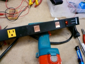
So, I picked up a power strip at a Big Box retailer and removed two of the outlets making room for a power supply, arduino mini, and a circuit to operate the relays.  I used a piece of copper I JB-welded in place to cover up the outlet holes.  The copper came from a roll of roofing flashing I got at the same big box many years ago.. super cheap and handy to have around!

Covering the removed outlet holes

Covering the removed outlet holes

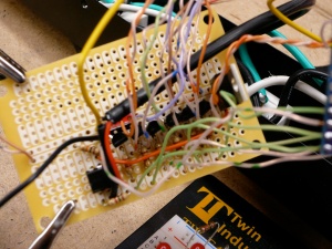
My original intent was to use a 555 chip for each relay/outlet, allowing each one to turn on and off one second apart.  I muddled through the design for that, ordered the parts and perf boarded up the first two modules.  At this point, although they were functional I realized a few things:

  • Point-to-point wiring takes some advanced planning
  • I stink at ‘bridging’ pads on purpose as required on the perf board I used
  • Repeating this module 4 more times was not my idea of a good time
  • I would not have enough room for all 6!

So I bailed on that design and ordered my first Arduino board to continue the project.  Picture documenting the 555 dead end:

555 on perf board

555 on perf board

For anyone who hasn’t used an Arduino yet you are missing out on some good fun.  Having a bread board circuit with the proper delay being generated by the Arduino in under an hour was impressive.  I still had to do some perf board work to get the transistors in place to drive the relays and provide a home for the opto-isolator which keeps the pre/pro electronics isolated from everything else.  For those observant folks looking for the diodes they are attached directly to each relay, but in hindsight it would have been easier to have them on the perf board as well.

Transistor driver board

Transistor driver board

Arduino wired to transistors

Arduino wired to transistors

This all buttoned up pretty nice in the power strip chassis.  I cut up a water bottle and put plastic around the electronics to keep any inadvertent grounding from occurring.  I did cheat on the power supply a bit and instead of making one, I took one from an old external HDD chassis as it slipped inside the power strip snugly.  I just wired the 120v in the strip, as there was plenty around!

Electronics all buttoned up

Electronics all buttoned up

And an admittedly crummy video of it in action..